
Continuing the VXLAN series, we are moving from Layer 2 extension into routing and shared gateway design. I decided to do lab 3 and 4 together because it easier to follow when they are shown as one progression from routed VLANs to shared gateways. The first two VXLAN labs focus on Layer 2 extension: map a local VLAN to a VNI, use the loopback as the VTEP source, and replicate flood traffic toward the remote VTEPs. These labs add the Layer 3 edge to that overlay. Lab 3 shows what changes when the VTEPs also route between stretched VLANs. Lab 4 keeps the same overlay, but changes the host gateway model so the gateway IP is no longer tied to a specific VTEP.
Lab Progression
| Lab | Main topic | Result |
|---|---|---|
vxlan/1-single | Single VLAN over VXLAN | One VLAN is mapped to one VNI and stretched across the underlay |
vxlan/2-complex | Multiple VLANs and VNIs | Multiple bridge domains are mapped to VNIs, with per-VNI flood lists |
vxlan/3-irb | VXLAN with routed VLAN edges | The VTEPs route between VXLAN-backed VLANs |
vxlan/4-anycast | VXLAN with shared gateways | Hosts use the same gateway IP on both VTEPs |
Topology
Labs 3 and 4 use the same two-switch, four-host topology.
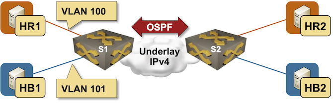
| Device | Role |
|---|---|
s1 | Arista cEOS switch and VTEP |
s2 | Arista cEOS switch and VTEP |
hr1 | Linux host in the red VLAN, connected to s1 |
hr2 | Linux host in the red VLAN, connected to s2 |
hb1 | Linux host in the blue VLAN, connected to s1 |
hb2 | Linux host in the blue VLAN, connected to s2 |
VLAN and VNI Plan
| VLAN name | VLAN ID | IP subnet | VNI |
|---|---|---|---|
red | 100 | 172.16.10.0/24 | 10010 |
blue | 101 | 172.16.11.0/24 | 10011 |
Host Addressing
| Host | VLAN | IP address | Attached switch |
|---|---|---|---|
hr1 | red | 172.16.10.3/24 | s1 |
hr2 | red | 172.16.10.4/24 | s2 |
hb1 | blue | 172.16.11.5/24 | s1 |
hb2 | blue | 172.16.11.6/24 | s2 |
Underlay Addressing
| Switch | Loopback0 | Interswitch link |
|---|---|---|
s1 | 10.0.0.1/32 | 10.1.0.1/30 |
s2 | 10.0.0.2/32 | 10.1.0.2/30 |
Gateway Models
The main difference between Lab 3 and Lab 4 is the host default gateway model.
| VLAN | Lab 3 gateway on s1 | Lab 3 gateway on s2 | Lab 4 shared gateway |
|---|---|---|---|
red | 172.16.10.1 | 172.16.10.2 | 172.16.10.42 |
blue | 172.16.11.1 | 172.16.11.2 | 172.16.11.42 |
In Lab 3, the gateway address depends on the VTEP where the host is attached. This is enough to test IRB, but the host first-hop address is location-specific.
In Lab 4, the gateway address belongs to the VLAN, not to one physical switch. Both VTEPs answer for the same gateway IP and MAC, so a host keeps the same first-hop address regardless of which VTEP it is attached to.
Without an anycast gateway, the stretched VLAN does not have a consistent first-hop router. That becomes a problem when a host moves or when the gateway VTEP fails.
Assume a data center has two racks. Rack 1 is attached to s1, rack 2 is attached to s2, and VLAN 100 is stretched between them with VXLAN. A VM starts in rack 1 with this configuration:
IP address: 172.16.10.50/24Default gateway: 172.16.10.1If the VM moves to rack 2, the Layer 2 part still works because VLAN 100 is stretched. The VM can keep the same IP address. The problem is the gateway. If 172.16.10.1 exists only on s1, the VM is now attached to s2 but still has to cross VXLAN to reach its gateway on s1. That adds unnecessary overlay traffic, creates a dependency on the old rack, and can break off-subnet connectivity if s1 fails.
Using different gateway IPs on each VTEP avoids the hairpin, but creates a different problem: the VM gateway would need to change from .1 to .2 when it moves. That is not practical for normal host mobility.
Anycast gateway avoids both issues. Both VTEPs answer for the same gateway IP and MAC, so the VM can move from rack 1 to rack 2 without changing its gateway. After the move, s2 becomes the local first-hop router, and VXLAN is used only when the destination VLAN or host is remote.
Lab 3: Configure IRB
Lab 3 adds routing between the red and blue VLANs. Each switch becomes the default gateway for the hosts directly connected to it.
In the earlier VXLAN labs, the VTEPs only extended Layer 2 segments. A frame entered a VLAN on one switch, was mapped to a VNI, crossed the underlay, and came out in the same VLAN on another switch.
Lab 3 adds a routed edge to those VXLAN segments. The VTEPs still bridge red and blue across the underlay, but they also have IP interfaces in both VLANs. That allows each switch to route traffic between the two stretched VLANs before sending the packet back into the overlay.
Each switch has a gateway address in both VXLAN-backed VLANs:
| Switch | VLAN | SVI | Gateway IP |
|---|---|---|---|
s1 | red | Vlan100 | 172.16.10.1/24 |
s1 | blue | Vlan101 | 172.16.11.1/24 |
s2 | red | Vlan100 | 172.16.10.2/24 |
s2 | blue | Vlan101 | 172.16.11.2/24 |
The VXLAN behavior depends on where the destination lives:
| Traffic flow | Forwarding behavior |
|---|---|
hr1 to hb1 | Routed locally on s1 between Vlan100 and Vlan101 |
hr1 to hr2 | Bridged in VLAN 100, then carried over VXLAN |
hb1 to hb2 | Bridged in VLAN 101, then carried over VXLAN |
hr1 to hb2 | Routed on s1 from red to blue, then carried over VXLAN in VLAN 101 |
For cross-subnet traffic, the routing decision happens at the first VTEP. After routing, the packet is placed into the destination VLAN and VXLAN carries that VLAN to the remote switch if needed. VXLAN is still doing Layer 2 extension; the VLAN interfaces add the Layer 3 decision point at the edge of the overlay.
Configure SVIs on S1
configure terminalinterface Vlan100 ip address 172.16.10.1/24interface Vlan101 ip address 172.16.11.1/24endConfigure SVIs on S2
configure terminalinterface Vlan100 ip address 172.16.10.2/24interface Vlan101 ip address 172.16.11.2/24endLab 3: Configure Static VXLAN
After the VLAN interfaces are configured, local routing works on each switch. The remote hosts still require VXLAN because the red and blue VLANs exist on both sides of the routed underlay.
Configure Vxlan1 on both switches and map each VLAN to its VNI. The VNI is the overlay identifier that keeps the red and blue bridge domains separate while they cross the same routed underlay.
Configure VXLAN on S1
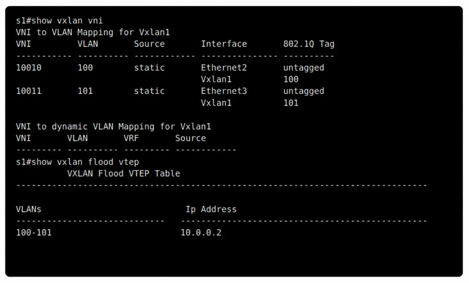
configure terminalinterface Vxlan1 vxlan source-interface Loopback0 vxlan vlan 100 vni 10010 vxlan vlan 100 flood vtep 10.0.0.2 vxlan vlan 101 vni 10011 vxlan vlan 101 flood vtep 10.0.0.2endConfigure VXLAN on S2
configure terminalinterface Vxlan1 vxlan source-interface Loopback0 vxlan vlan 100 vni 10010 vxlan vlan 100 flood vtep 10.0.0.1 vxlan vlan 101 vni 10011 vxlan vlan 101 flood vtep 10.0.0.1endCommand Reference
| Command | Purpose |
|---|---|
interface Vxlan1 | Creates the overlay interface used by the local VTEP |
vxlan source-interface Loopback0 | Uses the loopback as the source address for VXLAN encapsulation |
vxlan vlan 100 vni 10010 | Places local VLAN 100 into the red overlay segment |
vxlan vlan 101 vni 10011 | Places local VLAN 101 into the blue overlay segment |
vxlan vlan ... flood vtep ... | Defines the remote VTEP that receives flood traffic for that VNI |
The flood list is per VLAN/VNI. In this static VXLAN lab, the remote VTEP is configured manually for each stretched VLAN.
Lab 4: Anycast Gateway Objective
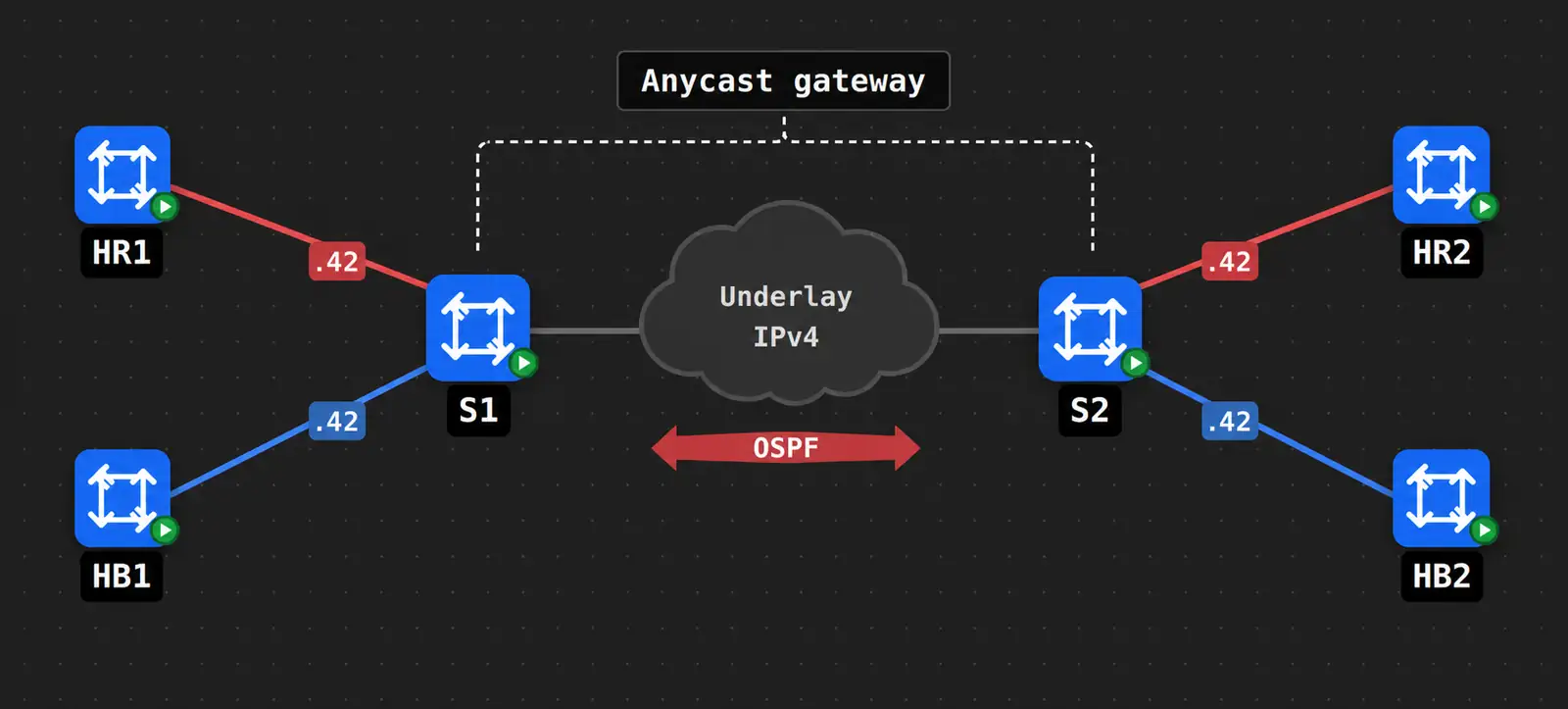
Lab 4 keeps the same VLANs, VNIs, underlay, and static flood lists. The change is the first-hop gateway.
In Lab 4:
redhosts use172.16.10.42as their gatewaybluehosts use172.16.11.42as their gateway- both switches answer for the same shared gateway addresses
From a VXLAN forwarding perspective, this makes each VTEP an active gateway for locally attached hosts. A host can send traffic to the same gateway IP on either side of the fabric. The local VTEP routes the packet, then VXLAN carries the destination VLAN across the underlay if the destination is remote.
Arista EOS implements this with a shared virtual router MAC address and per-VLAN virtual router IP addresses.
Lab 4: Configure the Anycast Gateway
Configure the same virtual MAC and virtual gateway IPs on both switches. The values must match on both VTEPs so hosts see the same gateway identity on either side of the VXLAN segment.
Configure Anycast Gateway on S1
configure terminalno ip icmp redirectip virtual-router mac-address 0200.cafe.00ffinterface Vlan100 ip virtual-router address 172.16.10.42interface Vlan101 ip virtual-router address 172.16.11.42endConfigure Anycast Gateway on S2
configure terminalno ip icmp redirectip virtual-router mac-address 0200.cafe.00ffinterface Vlan100 ip virtual-router address 172.16.10.42interface Vlan101 ip virtual-router address 172.16.11.42endBoth switches use the same virtual MAC and the same virtual IP addresses. Hosts see one consistent gateway address per VLAN. The directly attached VTEP still performs the routing locally.
Lab 4: Configure VXLAN
Use the same static VXLAN configuration from Lab 3. The anycast gateway changes the Layer 3 first-hop behavior, but it does not change the VLAN-to-VNI mapping or the static flood VTEP list.
Configure VXLAN on S1
configure terminalinterface Vxlan1 vxlan source-interface Loopback0 vxlan vlan 100 vni 10010 vxlan vlan 100 flood vtep 10.0.0.2 vxlan vlan 101 vni 10011 vxlan vlan 101 flood vtep 10.0.0.2endConfigure VXLAN on S2
configure terminalinterface Vxlan1 vxlan source-interface Loopback0 vxlan vlan 100 vni 10010 vxlan vlan 100 flood vtep 10.0.0.1 vxlan vlan 101 vni 10011 vxlan vlan 101 flood vtep 10.0.0.1endSummary
- VXLAN stretches the Layer 2 segments.
- Routing happens at the ingress VTEP when traffic moves between VLANs.
- After routing, VXLAN carries the destination VLAN across the underlay if the destination host is remote.
- Anycast gateway gives hosts a consistent default gateway across VTEPs.
- The static flood list is still manual in these labs; later EVPN labs replace it with a control plane.